2400IM & 3200IM Dehydrator Quick Start Guide
Congratulations on purchasing your new Dielectric IM (indoor mount) dehydrator. This quick start guide will detail the necessary steps to get your dehydrator quickly setup and working in your system.
Please refer to the complete user manual for further detail on each section of the guide and all safety warning information. Instruction booklet, IB-255, is available on our website at www.dielectrictechnologies.com
Site Requirements
115 VAC 3200IM model dehydrators require a 20A electrical circuit and ship with a 20A NEMA 5-20P plug. 115 VAC model 2400IM dehydrators ship with a standard 15A plug and may be used on a 15A circuit. A dedicated 20A circuit is recommended for each dehydrator.
The dehydrator dry air outlet has a standard ¼” female NPT threaded bulkhead fitting and included is a ¼” male NPT x 3/8” compression tube fitting for connecting into standard 3/8” poly tube.
The dehydrator must be located in an area that remains between 32-120 degrees Fahrenheit.
- Turn on the compressor circuit breaker and the on/off power switch.
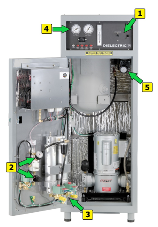
- After a 5 second delay the compressor will start running. Observe the backpressure gauge on the door to verify the correct dryer pressure setting. (50-55 PSI for 3200 models / 60-65 PSI for 2400 models.) If required, adjust accordingly using the backpressure regulator.
- While the compressor is actively running observe proper dryer purge valve operation by listening for a quick blast of air from the mufflers alternating every 30 seconds. NOTE: The humidity alarm will normally be active and air exhausting from the humidity bypass valve on the door during the initial startup and will generally clear within the first hour of operation. The excessive run alarm may illuminate during this time and is considered normal.
- After the dryer has sufficient runtime to clear the initial humidity alarm the humidity bypass valve will close and the unit will begin to fill the tank with dry air. Provided no dry air is leaving the outlet on the rear of the unit, the tank pressure should rise, and the unit will stop running once the OFF pressure setpoint is reached in the tank. (50 PSI for 3200 models, 60 PSI for 2400 models)
- Once the dehydrator has filled the tank and shut off, proceed to adjust the output line pressure using the line pressure regulator inside the unit. The regulator normally ships turned all the way down and the knob locked in place with a locknut on the threaded knob shaft. Loosen the locknut and turn the adjustment knob accordingly. Turning the knob clockwise will raise the line pressure, counter-clockwise will lower the pressure. The dehydrator has high and low line pressure alarms that come factory pre-set at 7PSI and 13PSI respectively. These are located on the electrical module mounted to the door and are user adjustable to meet the requirements of each individual installation. For complete instructions on alarm pressure switch adjustment refer to the instruction booklet.
Alarm Output Connections
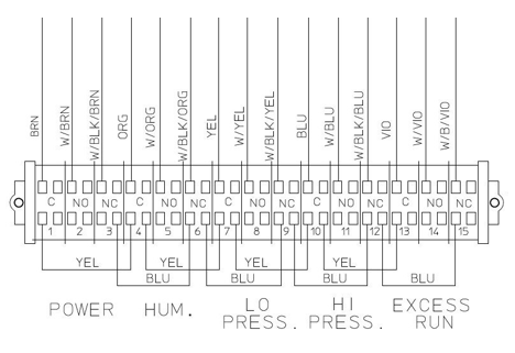
The dehydrator has a complete set of dry contact segregated alarm outputs to monitor all critical functions. These alarm outputs come factory wired with jumpers for use in “closed in alarm” configuration that combines all alarms in parallel to a single alarm set that can be monitored with one pair of alarm wires connected to terminal #1 and #15.
If you wish to monitor each alarm individually, remove the blue jumpers from the field connection side of the terminal block and wire to each individual desired alarm output’s either open or closed in connection terminal. Only a single common wire is required, and the yellow jumpers should remain in place.
To setup a single alarm pair to monitor the alarm output for “open in alarm” remove the blue jumper wires from the terminal block and move the yellow jumper wires so each alarm’s common and open in alarm terminal are wired in series. (Terminals 2-4, 5-7, 8-10 & 11-13, then connect the monitoring pair to terminal #1 and #14)