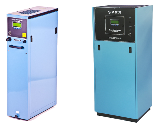
SmartTech Air Dryer Quick Start Guide
Congratulations on purchasing your new Dielectric SmartTech air dryer. This quick start guide will detail the necessary steps to get your air dryer quickly setup and working in your system.
Please refer to the complete user manual for further detail on each section of the guide and all safety warning information. Complete documentation on the installation, maintenance and repair of each unit is available by visiting our website at www.dielectrictechnologies.com.
Site Requirements: Before beginning the installation and startup of your air dryer please be sure you have the following installation requirements in place.
Electrical Supply
Operating with a supply voltage below 208V under load may result in compressor damage not covered under warranty.
- Model 5500ST dryers, 208-240VAC single phase 20A circuit.
- Model 11000ST dryers, 208-240VAC single phase 30A circuit.
- Model 16500ST dryers, 208-240VAC three phase 30A circuit.
- Model 22000ST dryers, 208-240VAC single phase 40A circuit. Min. 8AWG power cord not included.
- Model 33000ST dryers, 208-240VAC three phase 40A circuit. Min. 8AWG power cord not included.
- A 115VAC outlet near the dryer location is recommended for use with an ATS300+ dryer transfer system.
Water Drain
- 3/8” tube drain lines individually run from the back of each dryer into an existing floor drain is ideal. Drain lines that are run into an elevated drainage point above the air dryer are recommended to be first run into a small sump or condensate pump that will then pump the drainage water into the elevated drainage point.
- Water drain tubes that are tied together from more than one air dryer may present an issue of water from the active dryer back feeding into the standby air dryer. This configuration is not recommended.
Dryer Placement
- The air dryer should be placed in an area that provides for adequate ventilation and heat dissipation and is free from airborne contaminants or fumes from fuels or chemicals. The preferred ambient temperature range for the air dryer is 60-90 degrees Fahrenheit. The air dryer must never be located where the temperature will fall below 32 degrees.
- For 5500,11000 & 16500 dryers, allow 12 inches of clearance behind the air dryer and at least 36 inches in front of the dryer so it can be rolled forward for maintenance. Plan for enough extra slack in the power, water drain and air connections to allow the dryer to roll forward. These models do not require any clearance on the sides of the dryers and may be placed tight up against each other.
- For 22000 & 33000 dryers allow for 36 inches of space on all four sides of the air dryer for maintenance.
After confirming all site requirements are in place you may begin to install and start up the air dryer.
With all energy sources turned off and locked out, make the electrical supply connections. On models 5500-16500 connect the power cord on the dryer to your disconnect box or terminate with an appropriate plug. On models 22000-33000 install a power cord through the cable clamp on the bottom of the electrical connection box and make the power and ground connections on the input terminal block and ground stud.
Install the provided water drain tube fitting into the water drain outlet on the rear of the dryer and make all required tube connections into an appropriate drain.
Connect to either the low or high pressure dry air outlet using the provided nipple, elbow, check valve and barb fittings and ¾” hose (not included). The low pressure outlet is regulated by the line pressure regulator within the dryer. The high pressure outlet is an unregulated high pressure outlet (~26PSI) remove the factory installed plug to use the high pressure dry air outlet.
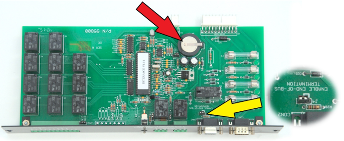
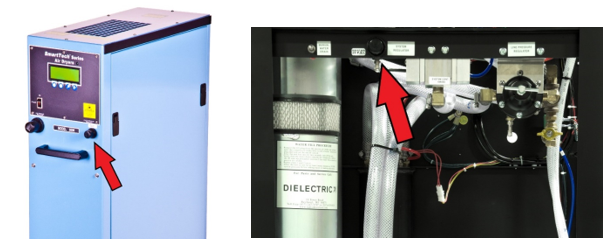
Remove the protective insulating tab which is located on the backup battery to activate the battery (RED arrow pictured below, tab not shown) on the ATS interface board located inside of the dryer. (In 5500-16500 dryers located in the rear inside of dryer above the heat exchanger. In 22000-33000 dryers located in the rear inside of dryer above the water separator tank.
ATS300 Connections
For dryers being used with an ATS300 transfer system, the dryer that will be the last in line of the serial communications cable daisy chain will require a jumper on the ATS interface board to be moved. With the power still off, remove the two screws that hold in the ATS interface board to the rear of the dryer and pull it out enough to move the jumper on the board. (YELLOW arrow pictured below). Only the last dryer in the line will require this jumper to be changed from the factory configuration. The jumper from the factory will be connected to the middle and the left pin. To set end of bus termination move the jumper over to the middle and right pin. Do not connect the serial cables from the ATS300 to the dryer(s) until later.
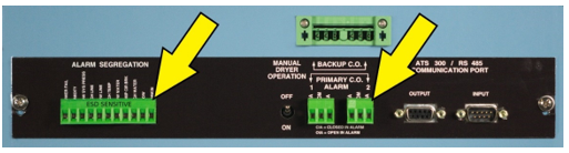
Connect any remote alarm monitoring cables to the dryer. There are several alarm options depending on the requirements of each installation but a typical connection consists of one alarm monitoring pair that will be wired into the “Primary C.O. alarm”. This is a common alarm output that will report on any of different alarms produced by the dryer. You may also wire individual outputs for each alarm by using the segregated alarm terminals on the left side of the interface board.
Proceed to begin filling the dryer with water by removing the red filler cap and using the fill port on the passive air intake (yellow arrow) and following the water fill procedure listed on the air intake canister. Use only drinking or tap water. DO NOT use distilled or deionized water in the air dryer.
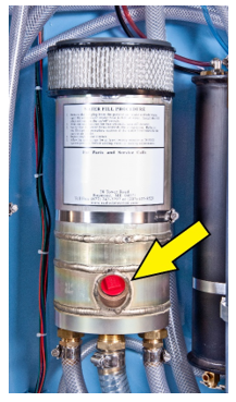
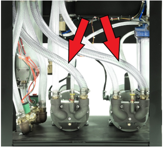
Once the wire reinforced tubes (red arrows) are completely filled with water, replace the fill cap, ensure the compressor circuit breakers on the dryer are turned on and proceed to turn on the dryer on/off switch. After a short delay the compressors will turn on and immediately begin circulating water into the system. DO NOT RUN THE COMPRESSORS FOR MORE THAN 2 SECONDS. Turn the power switch back off and repeat the procedure. NOTE: (For 16500 and 33000 dryers only) If the water in the wire reinforced tube did NOT get sucked into the compressor and pushed into the system; STOP and refer to the complete manual on startup instructions.
Once the dryer has been sufficiently filled with water allow the dryer to continue running and proceed to set the system pressure. The correct system pressure setting of the Smart Tech dryers is 28 PSI. Adjust as necessary with the system pressure regulator. (red arrows below) Once the system pressure is set you can adjust the line pressure regulator to the desired line pressure. The system pressure and line pressure may fluctuate slightly as you make adjustments and as the dryer stabilizes and warms up.
The display of the dryer will automatically cycle through the different screens showing pressure settings, temperature, humidity percentage, output airflow and dryer status. If you would like the display to remain on one screen press the “HOLD” button to temporarily pause the screen cycling.
Once the dryer is up and running proceed to go into the setup menu and set up the current date and time. Set up the desired high and low line pressure alarm settings. For dryers being setup on an ATS300 transfer system set up the dryer serial address by going into the menu option for “ATS BUS ADDRESS” and select the desired addressing. The factory default for all dryers is A1, the second dryer should be set for A2 and so on. You may now connect the ATS300 serial communications cables to the dryer if applicable. NOTE: the dryer may shut down when the ATS300 is connected until the ATS300 has been completely programmed.
Refer to the ATS300 manual for programming instruction manual located on the USB drive included with the ATS300 or by visiting our website at www.dielectrictechnologies.com. If the dryer shuts down when the ATS is initially connected, and you would like it to continue running, flip the small toggle switch on the ATS interface board for “manual operation” into the down (on) position to force the dryer to run. Once everything is set up return the manual operation switch to the normal off position.
After finishing dryer setup install the cabinet air filter(s) and replace all cabinet panels.