The SuperCAT4+ locators are capable of locating a Radiodetection sonde. Before attempting to locate a sonde ensure that the sonde’s batteries are fully charged. Radiodetection recommends using new or fully recharged batteries at the beginning of each day and preferably at the start of each job. Also check that the locator is operating at the same frequency as the sonde and that they are both working correctly.
To test the locator and the sonde, position the sonde at a distance equal to its rated depth range from the locator. Point the locator at the sonde with its blade parallel to the direction the sonde is travelling.
Check that the bar graph shows more than 50% at high sensitivity.
NOTE: The blade of the locator must be in line with the sonde; this is the opposite to Active line locate method.
Procedure
- Attach the sonde to the rod and insert it into the drain or duct to be mapped. Keep the sonde just in view.
- Hold the locator vertically directly over the sonde with the blade in line with the sonde’s orientation.
- Adjust the sensitivity of the locator to give a bargraph reading between 60-80%.
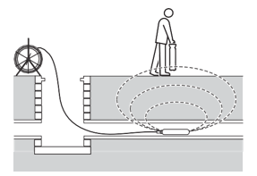
A sonde radiates a peak field from the center of its axis with ghost signals at each side of the peak. Move the locator to one side and then along the axis of the sonde forwards and backwards to detect the ghost signals.
Radiodetection recommends locating the ghost signals as finding them confirms the position of the main peak. To lose the ghost signals, reduce the sensitivity of the locator; this should leave only the main peak signal detectable.
With the locator sensitivity set as desired, propel the sonde along 1m (3-4 feet) and stop. Place the locator over the estimated position of the sonde and:
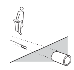
1. Move the locator backwards and forwards with the blade’s orientation parallel to the sonde.
2. Stop when the bar graph indicates a clear peak.
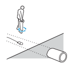
3. Rotate the locator as if the blade were a pivot, stop when the display indicates a clear peak response.
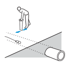
4. Move the locator from side to side until the bar graph indicates a clear peak.
5. When the locator locates a peak signal, it will automatically calculate the depth of the sonde. Observe the depth reading while moving the locator from side to side; the lowest reading will be the correct location.
Repeat each step in smaller increments with the locator blade resting on or near the ground. The locator should now be directly above the sonde with the blade parallel with the sonde; mark this position.
Propel the sonde a further 1m (3-4 feet) along the pipe and pinpoint and mark. Repeat the procedure along the route at similar intervals. Note, while tracking the sonde altering the locator’s sensitivity is not required unless the depth of the pipe, or the distance between locator and sonde changes.
Measure sonde depth
Pinpoint the sonde as previously described. Then rest the locator on the ground with the blade’s orientation parallel to the orientation of the sonde. Adjust the sensitivity to give a meter reading of 60% to 80% on the LCD’s bargraph.
NOTE: that the depth reading is the distance from the bottom of the locator blade to the center of the sonde and not to the drain or duct being located.
CAUTION: Ensure Depth readings are taken from peak readings.
Depth readings taken from ghost signal position will be incorrect.
Depth measurement is automatic. Depth reading will be displayed when the locator is moved slowly across the sonde. The shallowest depth reading displayed on the LCD is also the correct position directly above the sonde.
If the signal is too weak or unstable the locator unit will not calculate depth. In this case use a more powerful sonde or use the Pinpoint procedure described below.
Pinpoint Procedure.
1. Move the locator ahead of the sonde.
- Ensure the blade’s orientation is parallel with the sonde’s orientation.
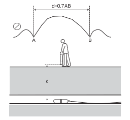
- Increase the sensitivity slightly to find the ghost signal. Note that between the main peak and ghost there is a Null or minimum.
2. Mark the Null or minimum position for reference.
3. Now move behind the sonde and repeat step 1.
4. Find the Null between the ghost and main peak. See points A and B on the diagram.
5. The higher the sensitivity of the locator the sharper the Null’s appear.
6. Measure the distance between points A and B and multiply by 0.7 to give an approximate depth measurement.
Warnings
Signal Overload
If the locator is used in areas where very large power signals are present, the signal bargraph will flash. In this condition the sensitivity control and depth function will not operate and you are advised to try lifting the locator to bring it out of the overloaded condition or use in a different location.

Deactivating
If required the StrikeAlert warnings can be temporarily disabled by pressing and holding the frequency selection button for the duration of the battery test bleep at switch on.
Live Plug Connector
Do not use the supplied Direct Connect leads to connect to live cables. Use the Radiodetection Live Plug Connector or Live Cable Connector. Failure to do so may result in injury or equipment damage.
Connection to live power cables should only be undertaken by qualified personnel.
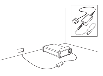
The optional Live Plug Connector applies the transmitter signal to a live domestic power socket and via the domestic wiring system on the service cable and the supply cable in the street. The signal should be detectable on the supply system to a few hundred meters each side of the point of application.
NOTE: Do not connect the transmitter to live cables without using a Live Plug Connector or Live Cable Connector.
Procedure
With the T1 switched off, connect the Live Plug Connector to the transmitter and then to the live domestic power socket. Where required switch on the power socket.
NOTE: The Live Plug Connector provides protection to 250V AC.
Sweep the site holding the locator upright at your side. Continue the sweep beyond the perimeter of the site. The presence of a buried conducting cable will be indicated by a tone emitted from the loudspeaker and a spike on the LCD’s bar graph.
Keep the locator’s blade vertical and move slowly backwards and forwards over the conductor. Reduce the sensitivity for a narrower response; this will allow you to pinpoint the conductor. With the locator use the meter deflection to aid pinpointing. Maximum meter deflection and audible volume from the speaker will indicate the position of the conductor.
When directly over the conductor and with the sensitivity level set for a narrow response, rotate the locator on its axis until the signal minimum is found. The blade is now parallel with the conductor.
Trace the conductor beyond the site and mark the position as required.
FlexiTrace™ - to locate non-metallic utilities
FlexiTrace is a 50m (164’) or 80m (260’) flexible conductive rod with a built-in sonde that can be inserted into non-metallic pipes and ducts to allow them to be located at depths of up to 3m (10’) FlexiTrace can be inserted into a pipe or duct as small as 12mm (½”) internal diameter, and with bends as tight as 250mm.
To use as a mouse, connect both transmitter leads to the FlexiTrace lugs. In this mode, only the tip of the FlexiTrace will be locatable. To trace the whole length, connect the red transmitter lead to a FlexiTrace terminal and ground the black lead, either to the earth stake or to an appropriate earthing point.