Model 600 & 850 Compressor Rebuild Kit
Installation Instructions
This guide will detail the necessary steps to take when performing the preventive maintenance or repair of the compressor in a model 600 and 850 dehydrator. Refer to the complete instruction booklet available at www.dielectrictechnologies.com for safety warning information before proceeding. When performing any work on the dehydrator be sure to isolate the unit from sources of pneumatic and electrical energy as well as drain any air from the internal tank of the unit.
TURN THE DEHYDRATOR OFF AND DISCONNECT FROM THE ELECTRIC POWER SOURCE BEFORE PERFORMING THE FOLLOWING PROCEDURES.
Disassembly
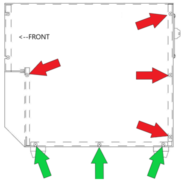
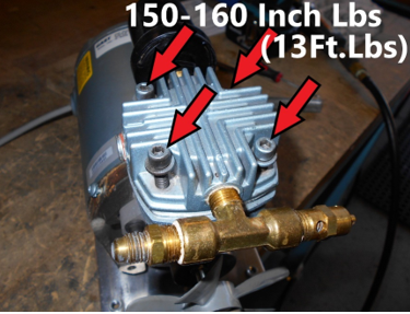
Start by removing the main cover on the unit. Completely remove the 4 screws indicated by red arrows. Loosen but do not completely remove the 3 screws indicated by green arrows. Repeat on the other side of the cover and then lift the cover from the unit.
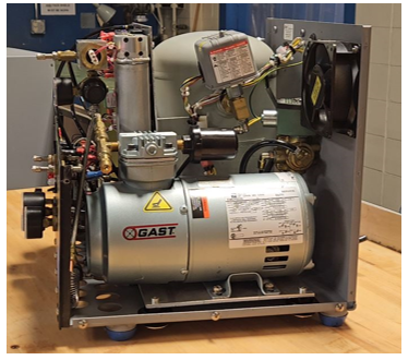
To allow for easier access, the compressor needs to be removed from the unit.
Position something under the unit to lift the dehydrator up and allow for easier access to unbolt the compressor mounts from underneath the unit. Using a 7/16” wrench, remove the 4 bolts and set aside.
Using a 9/16" wrench loosen and unscrew the compressor braided flex hose.
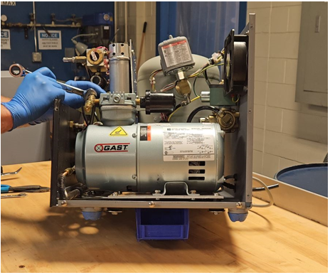
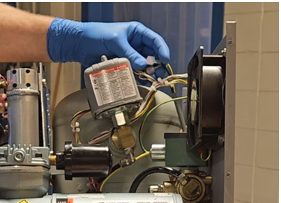
Follow the gray cord from the compressor up to the wire harness to locate and disconnect the three electrical connections to the compressor. Note: The two black wires do not have a specific polarity. You may need to remove zip ties securing the connection.
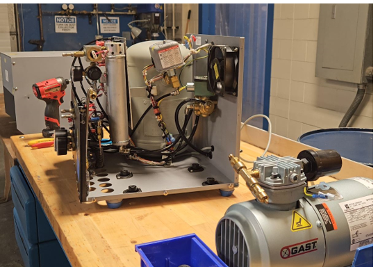
Remove the compressor from the unit to perform the rebuild.
Remove the fan shroud by unscrewing the 4 fan shroud screws. Note that fan shroud screws have thread locking compound on them and may be difficult to remove. Using a heat gun to apply heat to the screws can assist in removal.
Remove the 4 head bolts and pull off the cylinder head and valves.

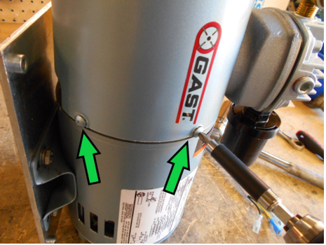
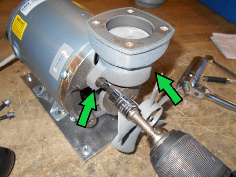
Remove the two cylinder bolts attaching the cylinder to the motor.
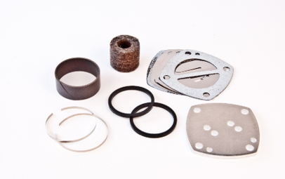
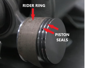
Remove the worn piston rider ring along with the metal and black plastic piston seals and discard.
Reassembly
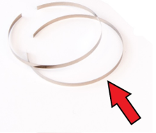
Install new piston seals. First place one of the thin metal rings into the piston groove.
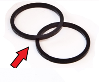
On top of the metal ring install one of the black piston seals. Ensure that the break in the metal ring is on the opposite side of the piston from the break in the black plastic seal. Repeat the steps on the second groove and ensure that the breaks in the black plastic seals are on opposite sides of each-other.
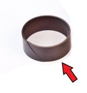
The piston rider ring is more difficult to install and will normally need to be held in place while reinstalling the cylinder over the piston. Fit the rider ring onto the piston and while holding it in place reinstall the cylinder over the piston seals while twisting the cylinder back and forth to get it to slide over the rider ring and down over the piston.
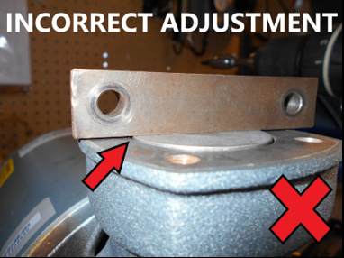
After sliding the cylinder down over the piston, reinstall the cylinder bolts finger tight. The cylinder has some up/down adjustment built into the mounting bolts and will need to be set correctly to ensure sufficient output flow and prevent piston and valve interference. Rotate the fan by hand to set the piston to its highest point of travel in the cylinder. Hold a straight edge across the top of the cylinder to ensure the piston does not protrude past the top of the cylinder.
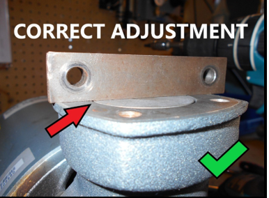
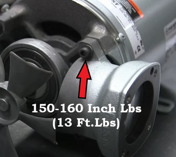
Tighten the cylinder bolts to 150-160 inch lbs. (Approx. 13 Ft. lbs. )
After torquing down the cylinder bolts- double check the cylinder height adjustment to ensure once again that the piston does not extend out beyond the cylinder. Severe compressor damage will result if the cylinder height is not adjusted correctly, and the piston is allowed to hit the valves when running.
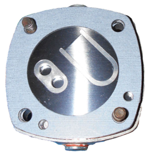
The new valves and valve plate need to be stacked on the cylinder head and reattached to the cylinder. Special attention must be paid to the orientation of the valves for correct compressor operation. Before reassembly ensure the head and cylinder are free from any old gasket material. Carefully remove with a razor blade or gasket scraper if required. It is helpful to hold two head bolts through the holes while stacking the valves for proper alignment.
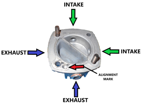
Locate the alignment hole in the head. This is not a through hole but used for valve orientation and is located directly next to one of the head bolt through holes.
Put the head gasket onto the head ensuring the center cross piece lines up with the center divider in the head casting. Note the extra hole in the gasket that aligns with the alignment mark cast into the head.
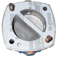
Place the exhaust valve onto the head. There is a small crease down the center of the valve, the raised side of this crease should be put towards the gasket. Once again note the alignment hole in the valve.
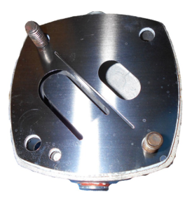
Install the vale plate on top of the exhaust valve. This is the thick metal plate included with the kit. This plate has two alignment marks so it must be observed that the intake and exhaust holes line up with the valves.
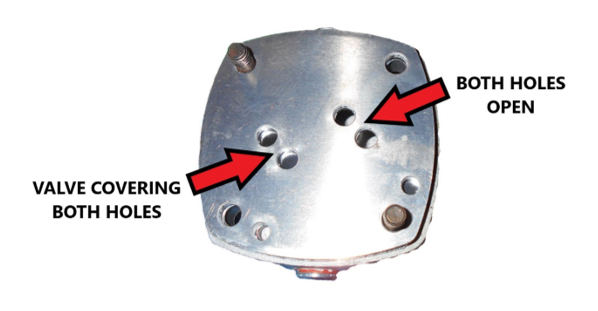
Install the intake valve plate. Note that this valve plate also has two alignment holes. The intake valve should be covering the two open holes in the previous valve plate.
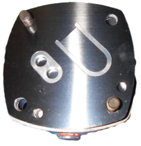
Install the cylinder gasket. This gasket has alignment marks but does not have any particular orientation and can be install in any direction. This concludes stacking all the valve components. Reattach the head to the cylinder paying special attention to the rotation of the head to the cylinder so that the intake filter and exhaust fittings are oriented correctly.
Tighten the cylinder bolts to 150-160 inch lbs. (Approx. 13 Ft. lbs. )
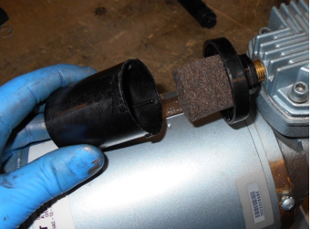
Change the intake felt filter. Remove the filter cover by turning it counterclockwise ¼ turn and lift off the base. Replace the felt filter and reinstall the cover.
Confirm the compressor can turn through its entire rotation without a piston hitting the valves in the head by manually turning the fan and feeling for resistance. The fan and compressor should spin freely without feeling any binding up at any point.
Reinstall the fan shroud and reinstall the compressor into the dehydrator. It can be normal for the compressor to make a louder than normal sound and have lower than normal output after restarting for the first time as the seals wear in. Normal compressor operation should resume within 1 minute of runtime. Checking for any air leaks around the head and valves is not required. Using a leak detection solution on the compressor head will produce a foam resulting from small amounts of air leaking out of the seals. This is considered normal.