ATS 304 & ATS 305 Interface Installation Instructions
This guide will detail the steps required to install the model ATS304 and ATS305 interface. The interface unit is designed for use with air dryers that are not capable of direct serial cable connection to a model ATS300 transfer system.
The model ATS304 and 305 function the same however they are designed for different operating voltages. The ATS304 part number 58235 is designed for use on 120VAC single phase circuits and the model ATS305 part number 58114 is designed for use on 208/230VAC single phase or 3 phase circuits.
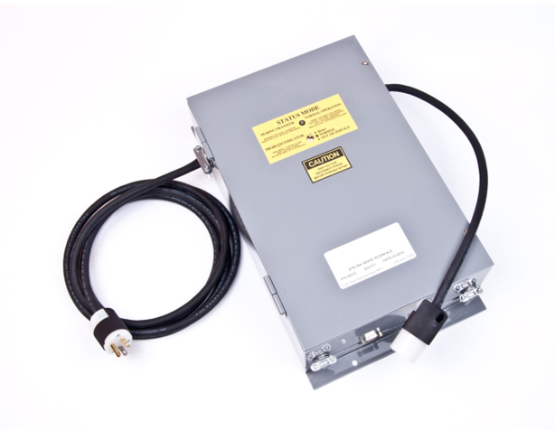
The ATS304 will come equipped with terminated input and output power cords pre-attached as shown below for use with a standard 20A 120V outlet. The model ATS305 comes with un-terminated cord to be hard wired into a disconnect or terminated with a plug of your choice.
Interface Operation:
The ATS304/305 interface functions by using a voltage sourcing digital input which sends out a 5VDC signal from the “COM” terminals on the input side of the board which goes into the air dryer alarm output common connection and back to the interface board through either the open or closed in alarm terminals on the dryer. When the alarm output from the dryer changes state during an alarm the interface board detects this change and registers an alarm which is then communicated to the ATS300 via the serial communications cable.
When the ATS304/305 senses an alarm it will not shut down the air dryer power but will allow the ATS300 to bring any available standby air dryers online and will mirror the alarm detected on the input to the dry contact outputs of the ATS304/305 board for use with remote monitoring systems.
Installation:
Before installing the ATS interface ensure that any power sources being worked on have been de-energized and locked out.
To begin installation of the interface, mount the unit in close proximity to the air dryer and the power supply. The power for the dryer from the power supply will be wired to the interface and then from the interface to the dryer.
On 120V units the appropriate plugs have been provided and the power from the dryer and to the interface need only to be plugged in.
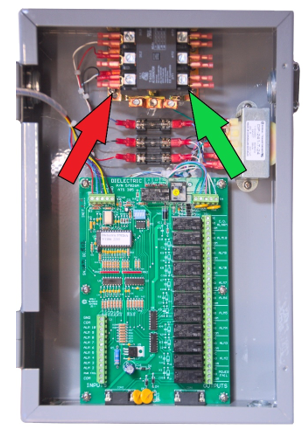
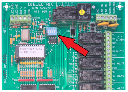
For 208/230V units, wire the input power from the supply to the contactor input side (red arrow).
For single phase units use only the 1L1 and 3L2 terminals. The 5L3 terminal will not be used.
For 3 phase units all 3 of the contactor input terminals will be used. Install the ground wire onto the provided ground lug below the contactor.
Wire the output from the interface into the air dryer from the output side of the contactor (green arrow) and the ground lug below the contactor.
Closed In Alarm Configuration
The next step to installing the interface is to wire the inputs to the board from the alarm output of the dryer. There are several ways this can be done but the most common way is to wire each segregated alarm from the dryer to its own input on the interface board. The example below shows wiring for “CLOSED IN ALARM” configuration which is the recommended default option. In this example a common wire goes from the board to the common connection on the dryer and 4 separate alarm outputs from the dryer are being used and monitored individually. In this example the connection on ALM 2 is closed which would show the ALM 2 input as being in alarm.
The ATS interface must not share dryer alarm outputs with other monitoring equipment or malfunction and damage will occur. Any existing alarm monitoring connections that may be on the dryer alarm outputs will need to be moved from the dryer and installed onto the output connections of the interface instead.
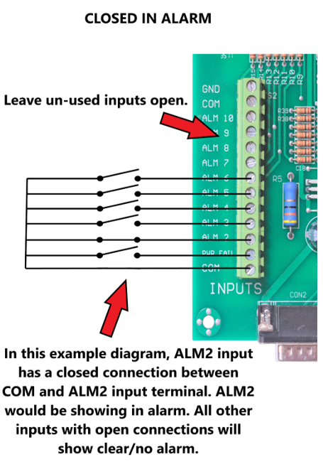
The PWR FAIL alarm is dedicated for power fail alarms only. If no power fail alarm is available, skip the PWR FAIL input by leaving it open and use the ALM2 input first.
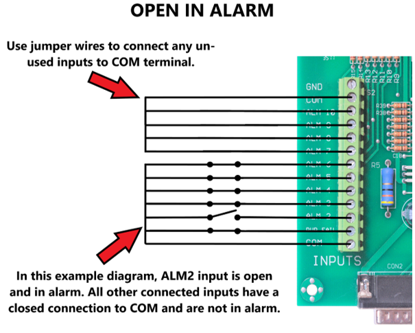
Open In Alarm Configuration
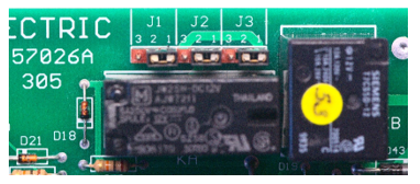
For “OPEN IN ALARM” configuration there are additional steps that must be taken to configure the interface board. There are 3 jumpers at the top of the board J1, J2 & J3 that must be moved from the factory default which connects pins 1&2 over to the setting for open in alarm by connecting pins 2&3 on each jumper.
The alarm wiring example below shows open in alarm configuration. In this configuration any alarm inputs on the board that are not being used must be connected to the common terminal using the supplied jumper wires. In the example below the ALM 2 input from the dryer would all show as being in alarm because the connection to the COM terminal is open.
NOTE: The PWR FAIL alarm is dedicated for power fail alarms only. If no power fail alarm is available, skip the PWR FAIL input by connecting it to the COM connection just like any other open inputs and use the ALM2 input first.
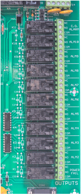
Any desired alarm monitoring connections to monitor dryer alarms can now be connected to the alarm output side of the interface board. You are not required to make any connections to the output side for the interface to work correctly.
Each individual alarm input has its own corresponding alarm output that will trigger as soon as an alarm input is sensed for that specific input. There is also a common alarm output labelled “C.O. ALARM” that will trigger when any of the alarm inputs are detected. If you only need to see if there is an alarm active on the ATS304/305 unit but do not need to know which specific alarm is active, then wire a single pair into the C.O. ALARM output connection.
If you would like to monitor each alarm output individually then wire an alarm connection to the output for each corresponding input you want to monitor.
- Note that the “COM” connections for each output are not connected together internally.
- To connect an alarm monitor for “CLOSED IN ALARM” use the “COM” and “NC” connections.
- For “OPEN IN ALARM” use the “COM” and “NO” terminals.
After the power, input and output connections to the interface have been wired, install the serial connection cable(s) to the bottom of the unit. In a system utilizing an ATS300 and two ATS304/305 interface units one serial cable will route from the ATS300 output to the first interface unit serial input and then from the first interface unit serial output to the second interface unit serial input.
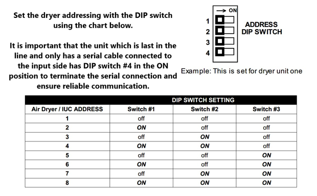
The serial addressing then will need to be set for each unit for the communications to work correctly. This is done by setting the dip switches located at the top of the interface board.
Testing & Troubleshooting:
After all connections are made and the addressing is set, turn the power onto the ATS304/305 interface to test operation. As soon as power is applied you will hear the contactor engage but the LED light on the front panel will not illuminate until the ATS300 connected to the interface has come online.
Test the alarm inputs by causing a dryer alarm and see that after approximately 3 seconds the ATS interface goes into alarm. Once the alarm has been cleared on the dryer the ATS interface will not show the alarm as being cleared until it is reset with the toggle switch.
Common mistakes when installing the interface generally arise when using the “OPEN IN ALARM” configuration on the input. In some cases when jumpers are installed on the un-used inputs there can be a poor jumper connection causing the unit to think the dryer is in alarm.
Another common fault that can occur with “OPEN IN ALARM” input configuration is because the 5VDC signal sent out from the board is low power and because mechanical relay contacts can see an increase in their contact resistance over time it is possible for the board to see this higher resistance connection as an open connection causing a false alarm or an intermittent alarm that appears to come and go without the dryer actually showing any alarm. This can be especially true if multiple alarm outputs from a dryer have been wired together in series. If you encounter this type of fault the best remedy is to rewire the input for “CLOSED IN ALARM” connections from the dryer.