Rebuilding Gast Dual Piston Compressors in all IM & PM Dehydrators
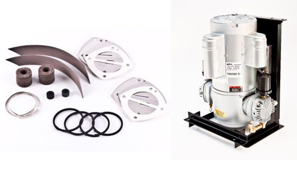
This guide will detail the steps to install the P/N 0027406501 rebuild kit into the Gast dual piston compressors used in all the Indoor Mount and Pole Mount Dehydrators.
As a general recommendation it is advised to rebuild annually or every 2000 hours. The environmental conditions which the compressor is subjected to will have a great impact on service intervals. The compressor may require shorter or longer intervals between rebuilds depending on the condition of the parts observed when the compressor is disassembled.
- Turn off the dehydrator and remove the compressor assembly. Disconnect the electrical plug and compressor flex hose. Remove the 4 nuts and lock washers holding the compressor frame to the cabinet and lift out the compressor assembly
- Remove the 4 bolts securing the compressor from the mounting frame.
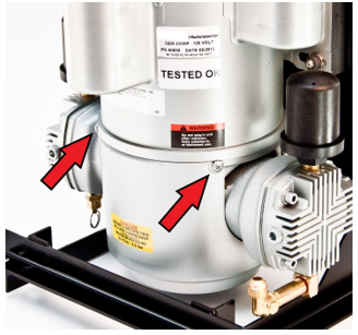
- For compressor models with fan shrouds, remove the fan shroud. The 4 screws (two front, two rear) securing the fan shroud may be difficult to unscrew due to thread locking compound. If required, applying heat to the screws with a heat gun can make removal easier.
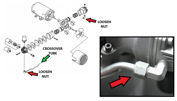
- Once the fan shroud has been removed, Use a ¾” wrench and fully loosen the nuts on both sides of the crossover tube that connects the two cylinder heads together.
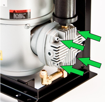
Begin disassembly of the piston. It is advised to disassemble and reassemble only one piston at a time in the event a reference of how all the pieces go back together is needed. Using a 3/16” hex key head bolts securing the compressor head to the cylinder. After removing the cylinder head bolts the cylinder head and valve plates can be removed. It is advisable to note the orientation of the valve plates as they were removed from the cylinder head. The most common user error when installing the rebuild kit is stacking and orienting the valve plates incorrectly.
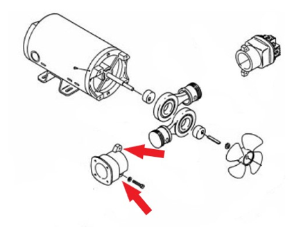
- Remove the two cylinder bolts attaching the cylinder to the motor frame and remove the cylinder. The cylinder walls where the piston rides should be smooth and shiny. If any scored or damaged areas are observed on the cylinder then the piston will also exhibit damage and will not be able to be repaired with this repair kit. Damage to the piston or cylinder typically will occur first on the side of the pump that has the pressure relief valve mounted to it as this side will see higher temperatures than the side with the output fitting.
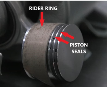
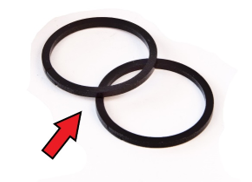
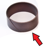
- After removing the cylinder and exposing the piston remove the old piston seals and the piston rider ring. The piston seals are the two small black rings and underneath will have thin stainless steel rings. Discard both. The rider ring is the larger brown/copper colored ring. Discard. Inspect the two grooves at the top of the piston for the piston seals for excess wear. A good piston groove will have well defined squared off 90 degree edges. Worn grooves will normally appear rounded and the groove at the top face of the piston will be worn very thin.
- Install new piston seals. First place one of the thin metal rings into the piston groove.
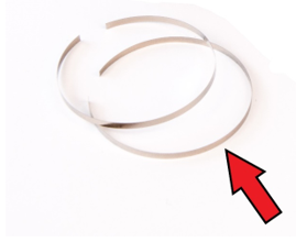
- On top of the metal ring install one of the black piston seals. Ensure that the break in the metal ring is on the opposite side of the piston from the break in the black plastic seal. Repeat the steps on the second groove and ensure that the breaks in the black plastic seals are on opposite sides of each-other.
- The piston rider ring is more difficult to install and will normally need to be held in place while reinstalling the cylinder over the piston. Fit the rider ring onto the piston and while holding it in place reinstall the cylinder over the piston seals while twisting the cylinder back and forth to get it to slide over the rider ring and down over the piston.
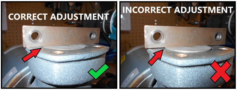
- After sliding the cylinder down over the piston, reinstall the cylinder bolts finger tight. The cylinder has some up/down adjustment built into the mounting bolts and will need to be set correctly to ensure sufficient output flow and prevent piston and valve interference. Rotate the fan by hand to set the piston to its highest point of travel in the cylinder. Hold a straight edge across the top of the cylinder to ensure the piston does not protrude past the top of the cylinder.
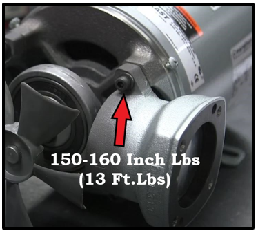
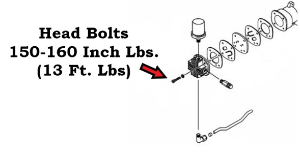
- Tighten the cylinder bolts to 150-160 inch lbs. (Approx. 13 Ft. lbs. )
- After torquing down the cylinder bolts- double check the cylinder height adjustment to ensure once again that the piston does not extend out beyond the cylinder. Severe compressor damage will result if the cylinder height is not adjusted correctly and the piston is allowed to hit the valves when running.
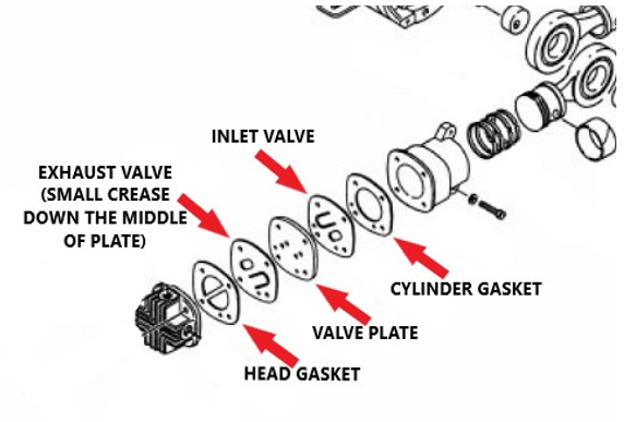
- The new valves and valve plate need to be stacked on the cylinder head and reattached to the cylinder. Special attention must be paid to the orientation of the valves for correct compressor operation. Before reassembly ensure the head and cylinder are free from any old gasket material. Carefully remove with a razor blade or gasket scraper if required. It is helpful to hold two head bolts through the holes while stacking the valves for proper alignment.
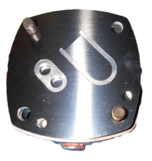
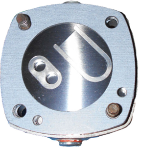
- Locate the alignment hole in the head. This is not a through hole but used for valve orientation and is located directly next to one of the head bolt through holes.
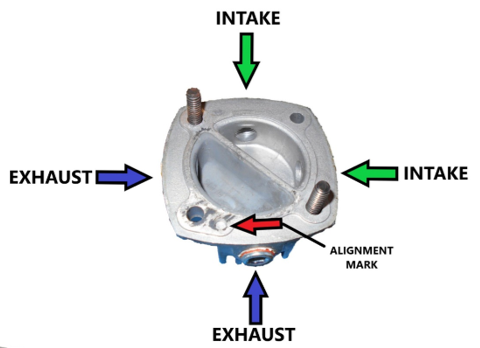
- Put the head gasket onto the head ensuring the center cross piece lines up with the center divider in the head casting. Note the extra hole in the gasket that aligns with the alignment mark cast into the head.
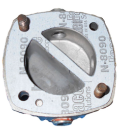
- Place the exhaust valve onto the head. There is a small crease down the center of the valve, the raised side of this crease should be put towards the gasket. Once again note the alignment hole in the valve.
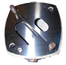
- Install the vale plate on top of the exhaust valve. This is the thick metal plate included with the kit. This plate has two alignment marks so it must be observed that the intake and exhaust holes line up with the valves.
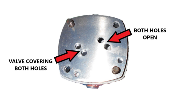
- Install the intake valve plate. Note that this valve plate also has two alignment holes. The intake valve should be covering the two open holes in the previous valve plate.
- Install the cylinder gasket. This gasket has alignment marks but does not have any particular orientation and can be install in any direction. This concludes stacking all the valve components. Reattach the head to the cylinder paying special attention to the rotation of the head to the cylinder so that all of the intake and exhaust fittings line up correctly.
When reinstalling the second head ensure you have the crossover tube in place with the new seals but not yet tightened down before bolting the head down.
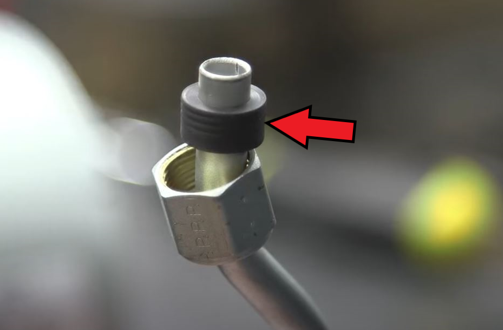
- Replace the rubber seals on the crossover tube with a new ones from the kit. Apply some O ring grease (silicone grease) to the rubber before installation if some is available. An O ring pick or screwdriver may be needed to remove the old seal from the compression nut.
- Torque the head bolts down in a cross pattern to 150-160 Inch Lbs / 13 Ft. Lbs
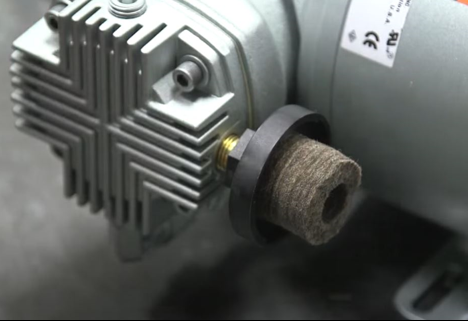
- Change the intake felt filter. Remove the filter cover by turning it counterclockwise ¼ turn and lift off the base. Replace the felt filter and reinstall the cover.
- After both cylinders and heads have been rebuilt and reinstalled, tighten the crossover tube nuts. There is no specific torque value, but they should be tight enough to feel the rubber seal compress without becoming difficult to turn with a wrench.
- Confirm the compressor can turn through its entire rotation without a piston hitting the valves in the head by manually turning the fan and feeling for resistance. The fan and compressor should spin freely without feeling any binding up at any point.
- Reinstall the fan shroud and reinstall the compressor onto the mounting bracket. Reinstall compressor into dryer and check that the compressor runs normally. It can be normal for the compressor to make a louder than normal sound and have lower than normal output after restarting for the first time as the seals wear in. Normal compressor operation should resume within 1 minute of runtime. Checking for any air leaks around the head and valves is not required. Using a leak detection solution on the compressor head will produce a foam resulting from small amounts of air leaking out of the seals. This is considered normal.
- If the compressor does not seem to be operating correctly after performing the rebuild by having no output the most often found issue is the valves were not installed correctly.