Minor & Major Repair Kit Installation Guide for Dielectric Water-seal Compressors
This guide will detail the necessary steps to rebuild the Dielectric water seal compressors using either the minor repair kit part number 47325 or the major repair kit part number 47328. Note that the two kits contain the same parts with the exception that the brass rotor is only included in the major repair kit. Rotor replacement is not normally required unless it is physically damaged or has been in service for many years.
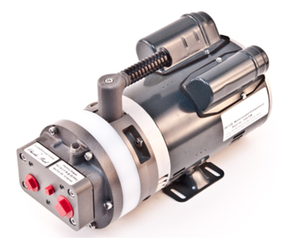
The Dielectric water sealed compressors are a proven design that will provide many years of reliable service. The service life before requiring a rebuild will vary based primarily on environmental conditions and individual operating conditions. Some factors that will indicate it is time to install a rebuild kit are that the dryer is no longer able to keep up with flow demands and provide adequate line pressure. Another indication that a rebuild may be required is if the compressor is cavitating which is often described as a groaning sound and accompanied by loss of line or system pressure. Any water leaking from the compressor head of near the front of the motor is also an indication that it is time to perform a rebuild.
In most cases installing the minor rebuild kit will restore the compressor output. If any damage or unusual wear is observed on the brass rotor then a major repair kit is recommended. If after installing the minor repair kit the compressor output is still low, replacement of the brass rotor is also recommended. If in doubt as to which kit is required, it is recommended to use the major repair kit.
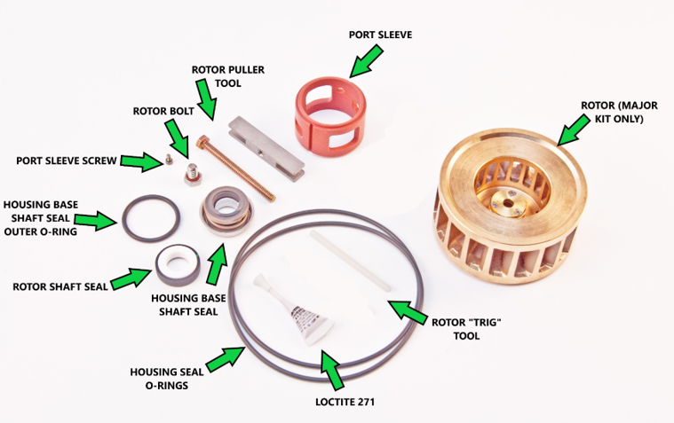
Repair Kit Components
Tools Required
- ¼” Hex wrench
- 7/64” Hex wrench
- 7/16” socket
- ½” socket
- Flat blade screwdriver
- O ring pick or a small flat blade screwdriver
- Torque wrench
- O ring grease
Disassembly
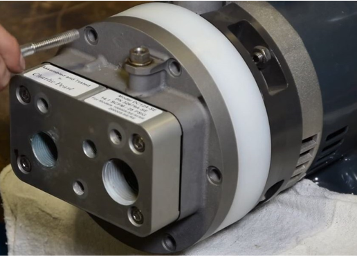
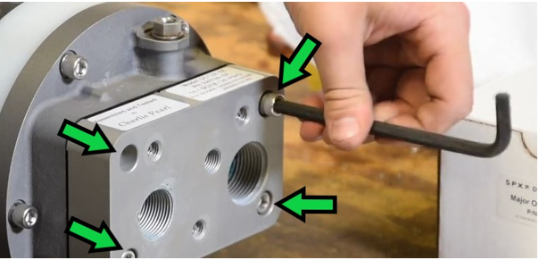
After removing the compressor from the dryer, begin disassembly of the pump head by first removing the 4 bolts that hold the front square manifold to the compressor port head. The purpose of removing this front manifold is to inspect the formed gasket located behind the manifold.
The gasket is not included in the rebuild kit and does not normally require replacement but should be inspected during a rebuild to ensure the gasket material remains pliable and does not show any signs of damage or tearing. If replacement is required, order part number 97674, formed gasket.
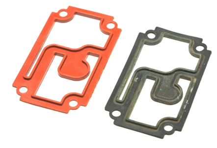
Formed gasket shown. Color of gasket varies by age. If the gasket is in good condition and pliable, then no further action is needed on this section of the compressor. Reinstall the gasket and reattach the front manifold to the compressor porthead.
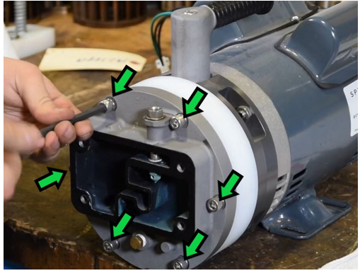
Remove the compressor porthead by removing the six bolts around the outside of the porthead assembly.
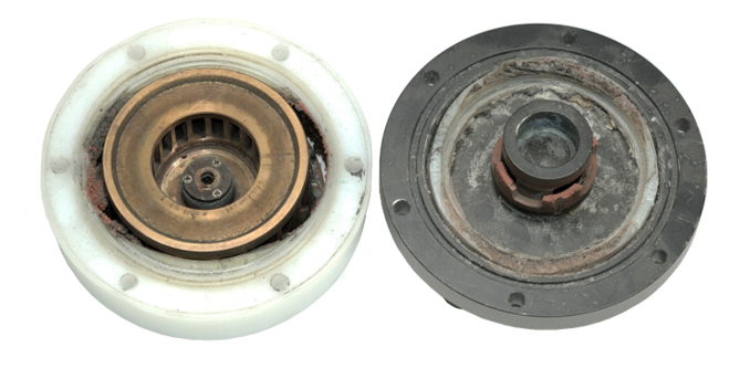
Inspect the parts for any obvious signs of damage or excessive wear. An example of a compressor that has been run dry and has been damaged beyond the scope of a repair kit show below.
Using an O-ring pick, remove the large outer o-ring from the porthead. Lubricate the replacement O ring with silicone grease and reinstall into the groove on the porthead.
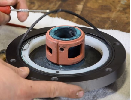
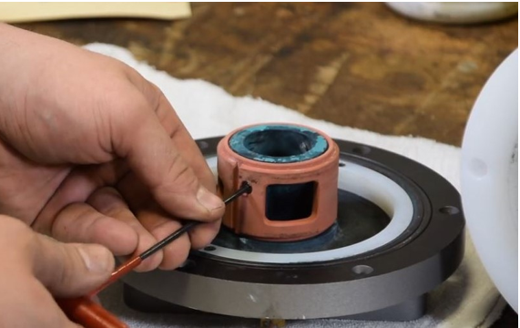
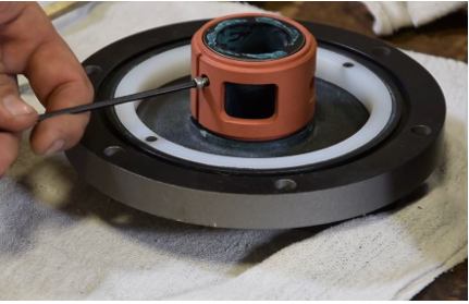
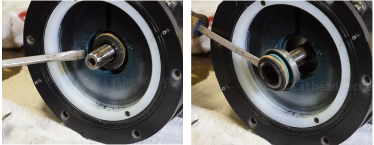
Using the 7/64” inch hex wrench remove the screw securing the portsleeve.
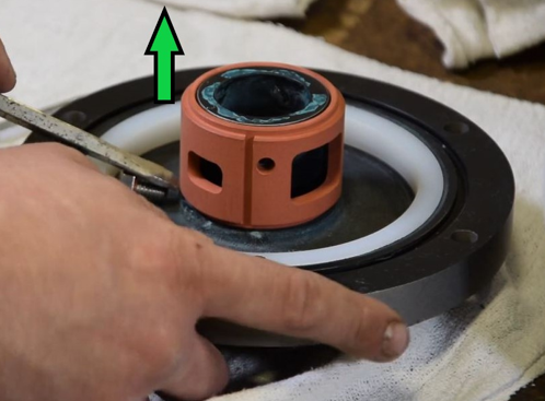
Pry the port sleeve off the port-head using the flat blade screwdriver. The rotor bolt included with the repair kit can be used as leverage to pry the port sleeve upward. Two flat blade screwdrivers can also be used on opposing sides to pry the port sleeve upward.
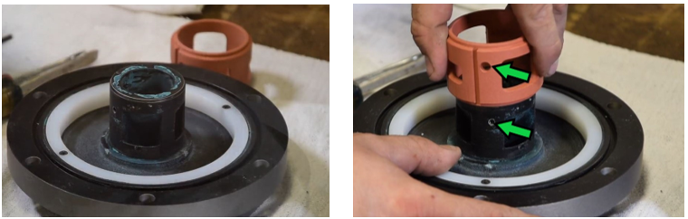
After removing the old port-sleeve, install the new port sleeve. To ease installation, wet the port sleeve with water. Pay special attention to the orientation of the threaded hole in the porthead and the hole in the portsleeve. Press the portsleeve down onto the shaft ensuring the two holes line up. If alignment is off, pry the portsleeve back up enough to rotate as needed and press it on again.
Reinstall the new port sleeve positioning screw.
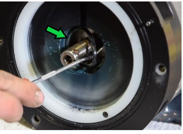
Next, remove the rotor from the compressor shaft. Install the supplied plastic dowel rod “trig” tool between the rotor and the housing which will jam between the two surfaces and prevent the rotor from turning in a counterclockwise direction.
Using the ½” socket remove the rotor bolt from the center of the rotor.
After removing the rotor bolt the rotor must be pulled from the motor shaft. Move the “trig” tool to the other side of the opening to prevent the rotor turning in a clockwise direction. And insert the supplied rotor puller tool into the vanes of the rotor so that the center bolt will go into the center hole in the motor shaft.
After installing the rotor puller tool use the 7/16” socket and tighten the rotor puller bolt which after making contact with the motor shaft will start pulling the rotor free from the shaft. Use caution, the rotor may drop free once it is loose.
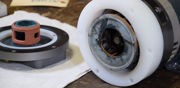
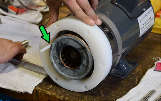
After the rotor is removed from the motor shaft, remove the housing by pulling it straight off of the housing base. There are two locating pins in the housing base and two corresponding holes in the housing for proper alignment during reassembly.
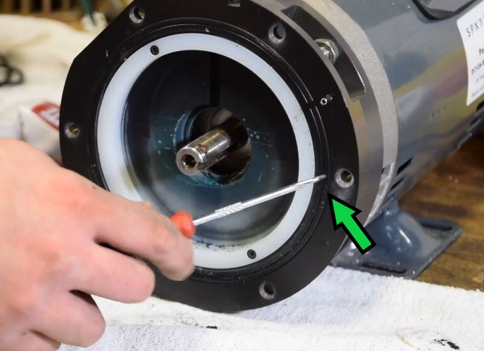
Using a flat blade screwdriver remove the rear shaft seal from the housing base and discard.
Using an O ring pick, remove the rear shaft seal O ring and discard. Lubricate the replacement O ring and install into the groove.
Remove the rear housing seal O ring and discard. Lubricate and install the new O ring seal in the housing base O ring groove.
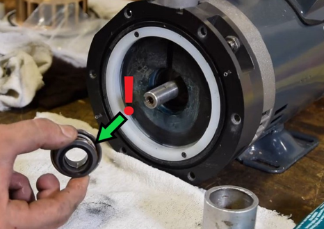
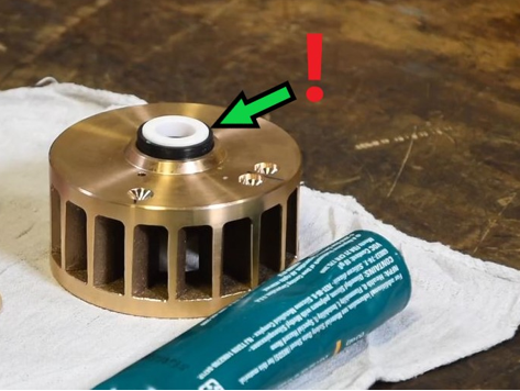
Insert the rear half of the shaft seal which contains the spring bellows. Use caution not to touch the glossy black ceramic sealing surface. Dirt or oils contaminating the surface can result in seal failure. The seal can be pushed into and seated in the rear compressor base with a large socket or gently using a punch, screwdriver or similar tool.
If installing the minor repair kit, remove the shaft seal from the rear of the rotor and replace with the new shaft seal with the white ceramic side up. Lubricate the rubber seal and press the seal into the rotor using a piece of paper or similar to protect the surface while pressing it into place. Use caution not to touch the white ceramic surface as any dirt or oils can result in seal failure. If installing the major repair kit discard the old rotor and seal and install the new seal into the new rotor.
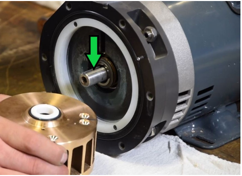
Reinstall the rotor to the motor shaft. Note: the motor shaft keyway and the key installed in the center of the rotor must line up for the rotor to be able to installed onto the shaft. It may be necessary to tap the rotor back onto the shaft using a rubber mallet.
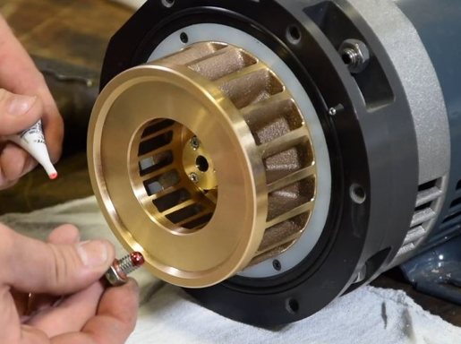
Apply a drop of the included Loctite 271 thread-locker to the new rotor bolt and install the bolt.
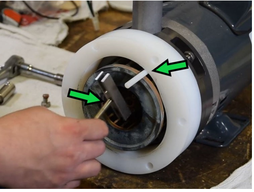
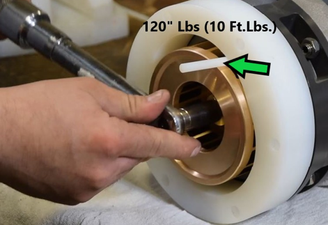
Reinstall the housing body onto the compressor base, align the two locating pins with the corresponding locating holes in the housing body. Use the rotor “trig” tool (green arrow) to bind the rotor and prevent it from rotating while torquing down the rotor bolt. The required torque is 120 Inch Lbs or 10 Ft. Lbs.
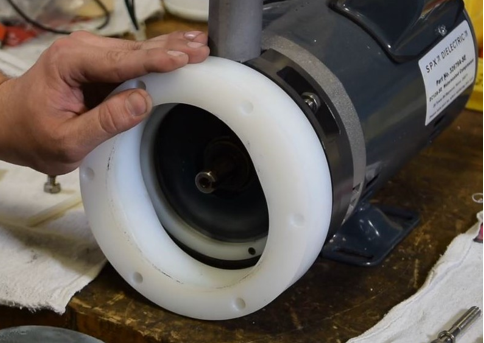
Reinstall the port head onto the compressor and install the 6 bolts. Torque the 6 port head bolts in a star pattern to 60 Inch Lbs, or 5 Ft. Lbs. The compressor has now been rebuilt and can be reinstalled. After reinstalling the compressor ensure that the compressor has been primed with water before starting the dryer by refilling the dryer with water until the entire compressor intake hose has been filled with water.